Orange Pi 3 LTS
You can use the Orange Pi 3 LTS, an SBC based on the Allwinner H6 SoC. Your board provides a 26-pin GPIO header and is supported by MainsailOS through an Armbian-based image.
Board Overview
| Property | Value |
|---|---|
| SoC | Allwinner H6 |
| RAM | 2 GB |
| Base Image | Armbian CLI |
| GPIO Header | 26-pin |
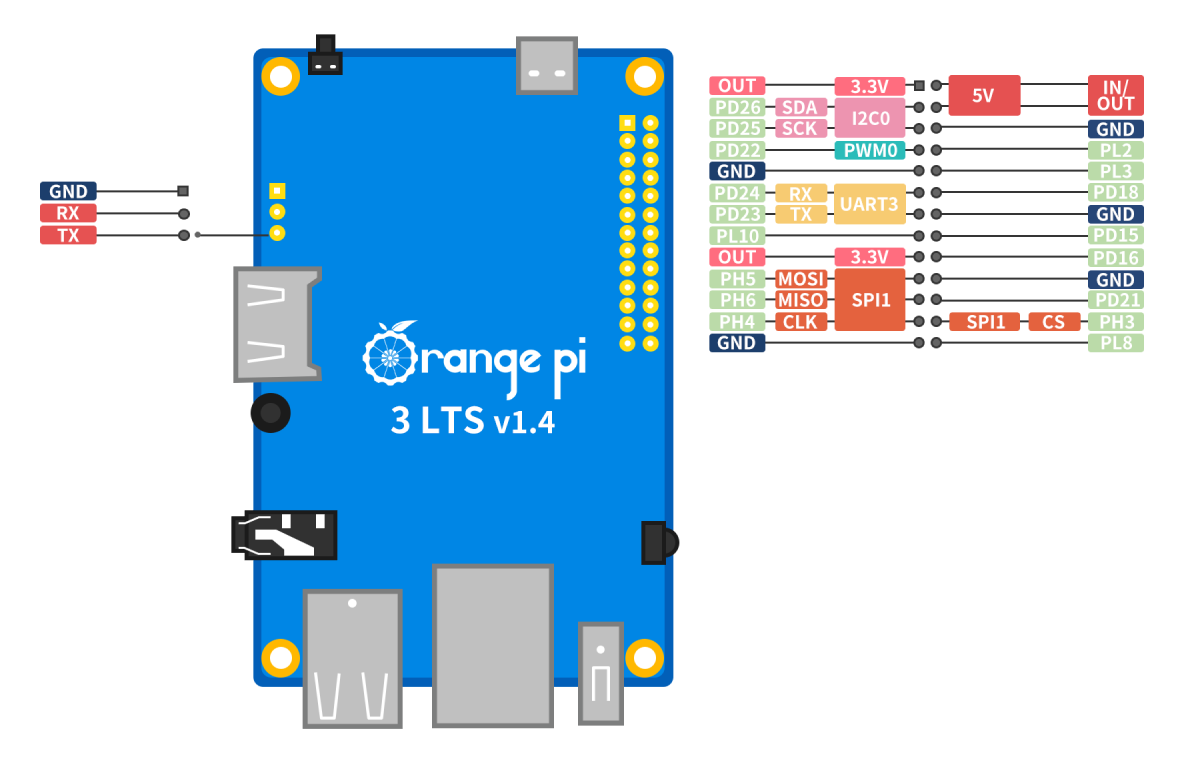
GPIO Pinout
GPIO Chip
When using GPIOs with the Linux MCU in Klipper, you need to identify the correct GPIO chip and line number for each pin. The H6 SoC exposes two GPIO controllers:
| GPIO Chip | Controller | Ports |
|---|---|---|
gpiochip0 |
r_pio | PL |
gpiochip1 |
pio | PA–PH |
Header Pin Mapping
The following table lists all GPIO pins on the 26-pin header with their Klipper pin references:
| Pin Name | GPIO Chip | Line | Klipper Pin |
|---|---|---|---|
| PD15 | gpiochip1 |
111 | host:gpiochip1/gpio111 |
| PD16 | gpiochip1 |
112 | host:gpiochip1/gpio112 |
| PD18 | gpiochip1 |
114 | host:gpiochip1/gpio114 |
| PD21 | gpiochip1 |
117 | host:gpiochip1/gpio117 |
| PD22 | gpiochip1 |
118 | host:gpiochip1/gpio118 |
| PD23 | gpiochip1 |
119 | host:gpiochip1/gpio119 |
| PD24 | gpiochip1 |
120 | host:gpiochip1/gpio120 |
| PD25 | gpiochip1 |
121 | host:gpiochip1/gpio121 |
| PD26 | gpiochip1 |
122 | host:gpiochip1/gpio122 |
| PH3 | gpiochip1 |
227 | host:gpiochip1/gpio227 |
| PH4 | gpiochip1 |
228 | host:gpiochip1/gpio228 |
| PH5 | gpiochip1 |
229 | host:gpiochip1/gpio229 |
| PH6 | gpiochip1 |
230 | host:gpiochip1/gpio230 |
| PL2 | gpiochip0 |
2 | host:gpiochip0/gpio2 |
| PL3 | gpiochip0 |
3 | host:gpiochip0/gpio3 |
| PL8 | gpiochip0 |
8 | host:gpiochip0/gpio8 |
| PL10 | gpiochip0 |
10 | host:gpiochip0/gpio10 |
Pins with Dedicated Functions
Some header pins serve dedicated roles (UART, SPI, I2C). Avoid using them as general-purpose GPIOs if the corresponding overlay is enabled. Refer to the GPIO Pinout diagram for pin functions.
Calculating GPIO Line Numbers
Allwinner SoCs use a simple formula to convert pin names (e.g., PH3) to GPIO line numbers:
Where port base values are: PA=0, PB=32, PC=64, PD=96, PE=128, PF=160, PG=192, PH=224, PL=0.
Note
Port PL belongs to gpiochip0 (r_pio) and starts at base 0. All other ports belong to gpiochip1 (pio).
Example: PH3 → port base 224 + pin 3 = 227 → Klipper pin: host:gpiochip1/gpio227
UART
UART3 is enabled by default in MainsailOS via the uart3 device tree overlay. The UART is immediately available
after the first boot.
| Interface | Device Path | Overlay | TX Pin | RX Pin |
|---|---|---|---|---|
| UART3 | /dev/ttyS3 |
uart3 |
PD23 | PD24 |
Cross the TX/RX Lines
The TX pin of the SBC connects to the RX pin on the MCU, and vice versa.
Debug UART
The Orange Pi 3 LTS has a dedicated 3-pin debug UART header (GND, RX, TX) on the board. This is intended for serial console access and is not suitable for MCU communication.
SPI
SPI1 is enabled by default in MainsailOS via the spi-spidev1 device tree overlay and the spi-dev kernel module.
It is pre-configured for use with accelerometers for
Input Shaper.
The SPI device is available at /dev/spidev1.0.
| Function | GPIO Pin |
|---|---|
| MOSI | PH5 |
| MISO | PH6 |
| SCLK | PH4 |
| CS | PH3 |
Example Klipper configuration for an ADXL345 accelerometer:
CS Pin
The PH3 pin maps to gpiochip1/gpio227. See the Header Pin Mapping for all pin
references.
I2C
I2C0 is enabled by default in MainsailOS via the i2c0 device tree overlay. The I2C device is available at
/dev/i2c-0.
| Interface | Overlay | Device Path | SDA Pin | SCL Pin |
|---|---|---|---|---|
| I2C0 | i2c0 |
/dev/i2c-0 |
PD26 | PD25 |
In your Klipper configuration, use i2c_bus: i2c.0:
I2C Bus Number
The overlay name and the actual /dev/i2c-* device number may differ. Always verify with ls /dev/i2c-* after
enabling the overlay and rebooting.
Further Resources
- Orange Pi 3 LTS — Official Page
- Armbian Documentation
- Klipper RPi Microcontroller — Klipper Linux MCU guide