Orange Pi 4 LTS
You can use the Orange Pi 4 LTS, an SBC based on the Rockchip RK3399 SoC. Your board provides a 26-pin GPIO header and is supported by MainsailOS through an Armbian-based image.
Board Overview
| Property | Value |
|---|---|
| SoC | Rockchip RK3399 |
| RAM | 3 GB / 4 GB |
| Base Image | Armbian CLI |
| GPIO Header | 26-pin |
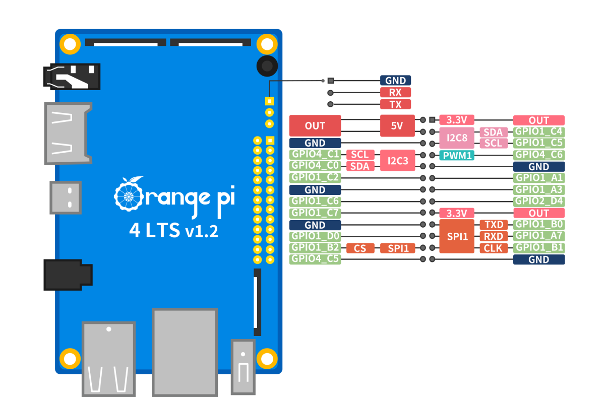
GPIO Pinout
GPIO Chip
When using GPIOs with the Linux MCU in Klipper, you need to identify the correct GPIO chip and
line number for each pin. The RK3399 SoC has 5 GPIO banks (GPIO0 through GPIO4), each exposed as a separate
GPIO chip (gpiochip0 through gpiochip4) with 32 lines each, organized in groups A–D (8 pins each).
Header Pin Mapping
The following table lists all GPIO pins on the 26-pin header with their Klipper pin references:
| Pin Name | GPIO Chip | Line | Klipper Pin |
|---|---|---|---|
| GPIO1_A1 | gpiochip1 |
1 | host:gpiochip1/gpio1 |
| GPIO1_A3 | gpiochip1 |
3 | host:gpiochip1/gpio3 |
| GPIO1_A7 | gpiochip1 |
7 | host:gpiochip1/gpio7 |
| GPIO1_B0 | gpiochip1 |
8 | host:gpiochip1/gpio8 |
| GPIO1_B1 | gpiochip1 |
9 | host:gpiochip1/gpio9 |
| GPIO1_B2 | gpiochip1 |
10 | host:gpiochip1/gpio10 |
| GPIO1_C2 | gpiochip1 |
18 | host:gpiochip1/gpio18 |
| GPIO1_C4 | gpiochip1 |
20 | host:gpiochip1/gpio20 |
| GPIO1_C5 | gpiochip1 |
21 | host:gpiochip1/gpio21 |
| GPIO1_C6 | gpiochip1 |
22 | host:gpiochip1/gpio22 |
| GPIO1_C7 | gpiochip1 |
23 | host:gpiochip1/gpio23 |
| GPIO1_D0 | gpiochip1 |
24 | host:gpiochip1/gpio24 |
| GPIO2_D4 | gpiochip2 |
28 | host:gpiochip2/gpio28 |
| GPIO4_C0 | gpiochip4 |
16 | host:gpiochip4/gpio16 |
| GPIO4_C1 | gpiochip4 |
17 | host:gpiochip4/gpio17 |
| GPIO4_C5 | gpiochip4 |
21 | host:gpiochip4/gpio21 |
| GPIO4_C6 | gpiochip4 |
22 | host:gpiochip4/gpio22 |
Pins with Dedicated Functions
Some header pins serve dedicated roles (UART, SPI, I2C). Avoid using them as general-purpose GPIOs if the corresponding overlay is enabled. Refer to the GPIO Pinout diagram for pin functions.
Calculating GPIO Line Numbers
The RK3399 uses the naming format GPIOx_Yn, where x is the bank (0–4), Y is the group letter (A–D), and n is
the pin number (0–7). To calculate the GPIO line number:
GPIO line = group × 8 + pin
Where group values are: A=0, B=1, C=2, D=3. The bank number determines the GPIO chip (gpiochipN).
Example: GPIO1_B2 → chip = gpiochip1, line = 1 × 8 + 2 = 10 → Klipper pin: host:gpiochip1/gpio10
UART
UART is not enabled by default in MainsailOS for the Orange Pi 4 LTS because UART4 shares its pins (GPIO1_A7 and GPIO1_B0) with SPI1, which is pre-configured for accelerometer use. To use UART4 for serial MCU communication, you need to disable SPI1 first.
Edit /boot/armbianEnv.txt:
Replace the SPI overlay with the UART4 overlay and remove the SPI parameters:
# Change this:
overlays=spi-spidev
param_spidev_spi_bus=1

# To this:
overlays=uart4
#param_spidev_spi_bus=1
Then reboot. The UART device will be available at /dev/ttyS4.
| Interface | Device Path | Overlay | TX Pin | RX Pin |
|---|---|---|---|---|
| UART4 | /dev/ttyS4 |
uart4 |
GPIO1_A7 | GPIO1_B0 |
SPI1 No Longer Available
After switching to UART4, the SPI1 bus will no longer be available. Accelerometers that use SPI (e.g., ADXL345)
will not work until you switch back to the spi-spidev overlay.
Debug UART
The Orange Pi 4 LTS has a dedicated 3-pin debug UART header (GND, RX, TX) next to the 26-pin GPIO header. This is intended for serial console access and is not suitable for MCU communication.
SPI
SPI1 is enabled by default in MainsailOS. The spi-spidev overlay and spi-dev kernel module are pre-configured
for use with accelerometers for Input Shaper.
The SPI device is available at /dev/spidev1.0.
| Function | GPIO Pin |
|---|---|
| MOSI | GPIO1_B0 |
| MISO | GPIO1_A7 |
| SCLK | GPIO1_B1 |
| CS | GPIO1_B2 |
Example Klipper configuration for an ADXL345 accelerometer:
UART4 Pin Conflict
SPI1 shares its MOSI/MISO pins with UART4 (GPIO1_A7 and GPIO1_B0). You cannot use SPI1 and UART4 at the same time. To switch to UART4, see the UART section above.
I2C
I2C3 is available on the GPIO header at /dev/i2c-3 without any additional overlay configuration.
| Interface | Device Path | SDA Pin | SCL Pin |
|---|---|---|---|
| I2C3 | /dev/i2c-3 |
GPIO4_C0 | GPIO4_C1 |
In your Klipper configuration, use i2c_bus: i2c.3:
Further Resources
- Orange Pi 4 LTS — Official Page
- Armbian Documentation
- Klipper RPi Microcontroller — Klipper Linux MCU guide